Using the Interfacing Hemisphere Principle to Achieve Low Resistance Grounding Interfaces
Davis B. Chamblee - Vision Technologies, Inc.A low resistance grounding system has always been necessary for the safe and proper operation of electrical systems. The growing use and dependence upon computers and other electronic systems have made it an essential part of today’s modern facility. This paper will explore methods of obtaining the low-resistance ground interfaces required (and increasingly specified by equipment manufacturers) for the operation and protection of modern electronic systems
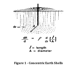
A ground electrode establishes a connection to earth by affecting a certain volume of earth. This volume has the shape of a half-buried sphere. or hemisphere. The size of this sphere is determined by the length of the electrode. Think of this interfacing Hemisphere [IH] as a series of concentric shells. with the innermost shells accounting for a proportionally greater amount of the connection to earth than the outer shells. See Figure 1 below.
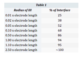
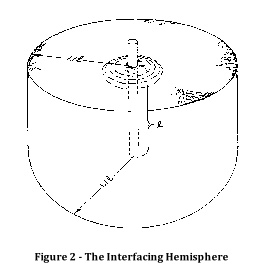
The entire connection to earth is contained within an IH with a radius of 2.5 times the length of the electrode. As seen in Figure 2. 95% of the connection to earth is contained within an IH with a radius of 1.1 times the length of the electrode. Other proportions are listed in Table 1 below.
The greatest influence on grounding resistance is soil resistivity. Different soils have widely varying resistivities (measured in ohm/meters), resulting in great differences in ground resistance from one location to another. For example, a conventional 10 ft. ground rod driven into soil measuring 100 ohm/meters will yield a resistance to ground of about 32 ohms. This same rod driven into 500 ohm/meter soil will measure about 170 ohms. The factors most greatly affecting soil resistivity are moisture, mineral content, and temperature.
While it would be impractical to replace the soil or alter these parameters over an entire site location, remember that 95% of our connection to earth is achieved In an area with a radius of 1.1 times the length of our electrode. If we can change one or more of the influencing factors in this area. we can have an impact on the soil resistivity and resulting ground Interface.
Vision Technologies has developed two products which assist in taking advantage of these principles. The Automatic Chemical Enhancing (ACE) electrode system adds both minerals and moisture to the earth surrounding the electrode. A 10 ft. ACE electrode in the 500 ohm/meter soil mentioned above would yield a ground resistance of approximately 27 ohms. This is a 600% improvement over a conventional driven rod. It is even lower than the driven rod would have delivered in the 100 ohm/meter soil.
As we discussed earlier. if we imagine the soil surrounding the electrode as concentric shells. the shells closest to the electrode have the greatest effect on the ground interface. We call this the Critical Cylinder. Replacing the soil within this Critical Cylinder with a low resistance material will result in a dramatic decrease in ground resistance. Vision Technologies Low Resistance Backfill [LRF] material is a natural day-based material with a resistivity of less than 2.5 ohm/meters. In a typical application, you might replace the soil in a Critical Cylinder with a radius of between 6 and 12 inches. In our example above. replacing a 6-inch radius Critical Cylinder would lower the ground interface resistance from 168 to 94 ohms. Still not great. but an improvement of over 55%.
The most cost-effective solution is a combination of these methodologies. The use of a chemically charged electrode in conjunction with a low resistance backfill provides the lowest possible resistance at the lowest installed cost. Table 2
shows a comparison of chemically charged electrodes versus conventionally driven rods, both with and without backfill, and the number of electrodes required to achieve a target ground resistance of 5 ohms In 500 ohm/meter soil.
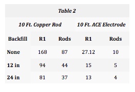
Backfill = Diameter of backfilled Critical Cylinder
R1 = Resistance of 1 electrode
Rods = Rods required to meet target
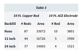
Grounding equations are based on the premise that the ill of various rods do not overlap to any significant degree; Le. all ground electrodes should be separated by at least 2 times their length. More often than not, multiple ground rods are required to achieve a target ground resistance. Multiple electrodes each have their own ll-I. whose overlap should be minimized. However. ignorance of this principle or limited available real estate will often cause these multiple rods to be placed too closely, thus compromising the earth connection. For example. Table 3 illustrates the amount of real estate in square feet required to implement each of the solutions given in Table 2. Using conventional rods alone, 87 rods requiring 33,072 sq. ft. of land would be required to obtain our
target of 5 ohms in the example 500 ohm/meter soil. Even using Low Resistance Backfill in a 24-inch diameter hole, it would take 37 conventional rods and 14,065 sq. ft. of land. Only four ACE electrodes in 24-inch holes backfilled with LRB and 1521 sq. ft. would be required. The labor alone to install the required number of conventional rods would give the cost advantage to the ACE electrode, but when the cost of real estate is factored in. it’s not even a contest.
In conclusion. the combination of chemically charged grounding electrodes and low resistance backfill materials enables a cost-effective, low-resistance grounding interface to be accomplished in almost any situation. There is no longer any excuse for allowing damage and erratic operation of electronic systems from lack of a stable grounding system.